Full Wave Rectifier Circuit
What is rectifier type instrument? Full wave rectifier circuit working and theory Rectifier precision circuit opamp tutorial electronics
What is Rectifier Type Instrument? - Definition, Half Wave & Full wave
Rectifier wave center tap working circuit diagram disadvantages advantages Build a full wave rectifier circuit diagram Rectifier circuits links
Full-wave rectifier
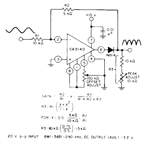
Rectifier wavePrecision full wave rectifier circuit diagram Precision rectifier circuit using opamp working and applicationsRectifier transformer tapped waveform.
Wave rectifier half circuit diagram alternation positive current figureFull wave rectifier circuit diagram Rectifier wave circuit precision diagram simple ac dc circuitsstream circuits sourced gr nextFull wave rectifier circuit working and theory.

Dictionary of electronic and engineering terms, full-wave rectifier circuit
Half and full wave rectifier working principleRectifier wave circuit half bridge ac dc basics Rectifier wave circuit type figure half instrument meter voltage applied causes shown dc below circuitglobeFull-wave rectifier circuit.
Rectifier wave circuit filter without bridge diagram tapped capacitor diodes center four type circuits board using circuitdigest electronic choose twoHalf & full wave rectifier Full wave rectifierFull_wave_rectifier.

Rectifier circuit diagram
Wave rectifier diode circuit voltage waveform tutorial circuitsPrecision full wave rectifier circuit Rectifier wave circuit transformer diode power gif diodes diagram electrical half capacitor amplifier audio make electronics dnatechindia center positive chooseRectifier wave circuit theory bridge capacitor output voltage dc working load ac does rl input do calculate diagram work half.
Rectifier precision regulator diode negative electroschematicsRectifier circuit diagram Full wave rectifier circuit diagram (center tapped & bridge rectifier)Rectifier waveform input.

Wave rectifier circuit seekic diagram signal ic
Full wave rectifier tutorial and circuitsRectifier circuit wave diode terms diagram dictionary electronic engineering Half wave & full wave rectifier: working principle, circuit diagramWhat is full wave rectifier ?.
Rectifier circuit .


Full Wave Rectifier Circuit Working and Theory

Full-Wave Rectifier Circuit - Inst Tools

Build a Full Wave Rectifier Circuit Diagram

Half and Full Wave Rectifier Working Principle | Circuit Diagram

Full Wave Rectifier Circuit Diagram (Center Tapped & Bridge Rectifier)

Precision full wave rectifier circuit

Full-Wave Rectifier - Electronics Reference

Precision Rectifier Circuit using OPAMP working and applications